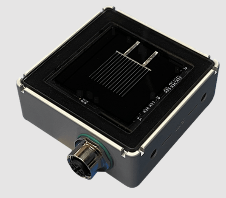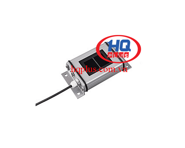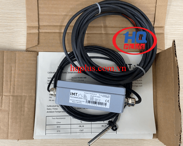

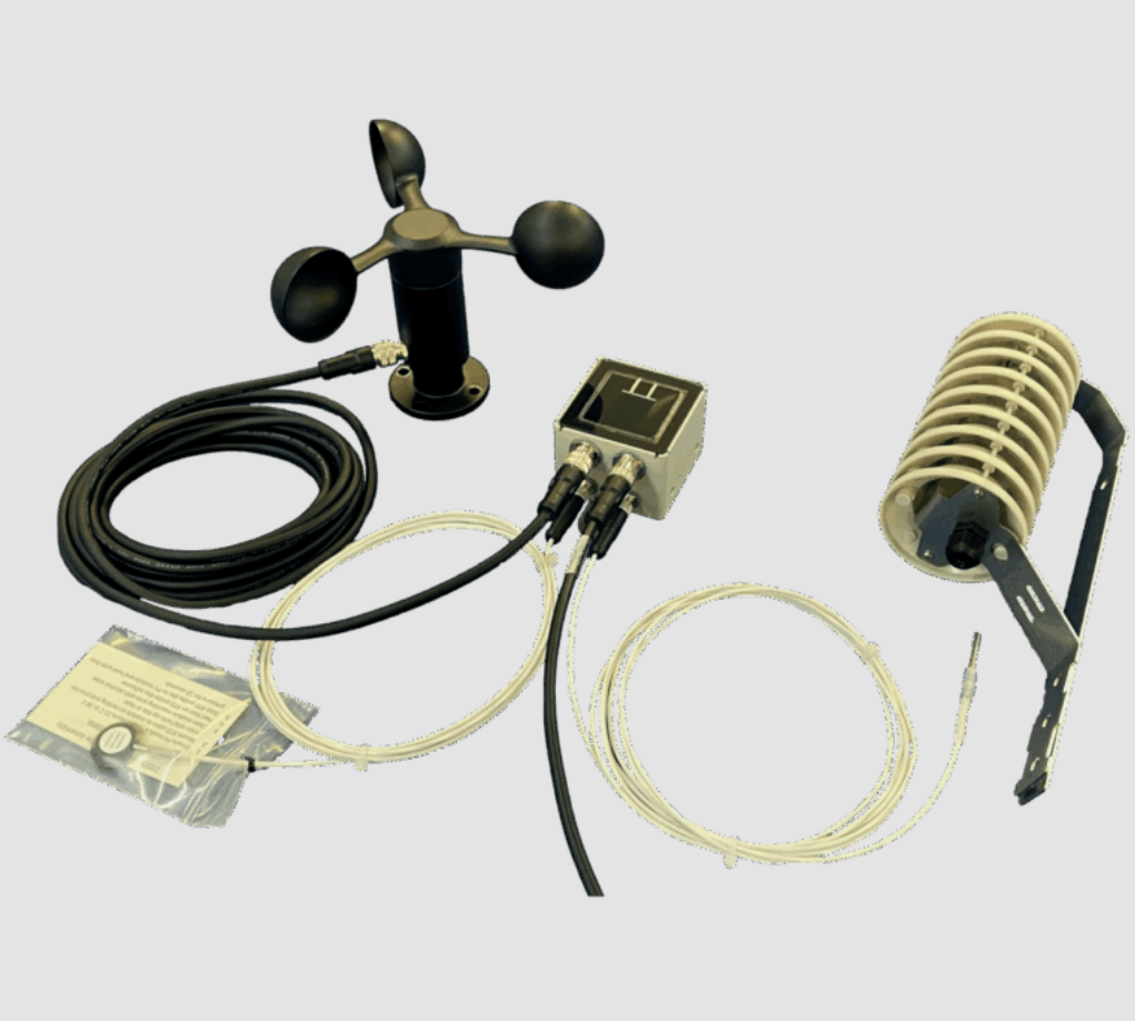


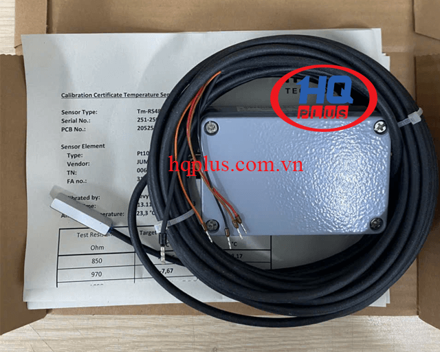
Digital Module Temperature Sensors Tm-RS485-MB
Giao hàng miễn phí toàn quốc
Hỗ trợ tư vấn kỹ thuật 24/7 (cả dịp Lễ, Tết)
Bảo hành nhanh chóng khi khách hàng phản hồi
Products code
: Tm-RS485-MBBrands
: Ingenieurbüro Mencke & TegtmeyerOrigin
: ĐứcProducts status
: Mơi 100%Product Price
: Liên hệ
Giá tốt hơn nơi đâu bạn thấy!
Digital Module Temperature Sensors Tm-RS485-MB
Safety Instructions
The installation and assembly of electrical equipment must be carried out by electrically qualified persons.
The sensor may not be used with equipment whose direct or indirect purpose is to prevent death or injury,
or whose operation poses a risk to humans, animals or property.
Warranty and Liability
The sensor is designed for the measurement of a surface temperature. The warranty is for 1 year from the date of
the invoice for the intended use. IMT Technology does not accept any liability for possible losses or damage due to the
incorrect usage of the sensor. Liability for consequential damages is excluded.
Mounting Instructions
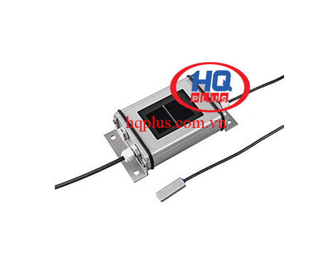
The sensor element is mounted by gluing the aluminium block directly to the measurement surface. The surface must be dry,
clean and degreased. Cleaning should NOT be done with glass cleaner, as some glass cleaners contain additives to prevent
soiling after cleaning and these additives also prevent adhesion. Isopropyl Alcohol or Ethanol is recommended for cleaning.
Temperature sensors shall be placed in representative locations to capture the range of variation and allow determination of
an eąective average. For crystalline silicon modules, select the centre of the centre-most cell within the module, or, when the
module is built with even numbers of rows or columns of cells, select one of the cells closest to the centre.
For bifacial modules, rear-side temperature sensors and wiring shall obscure < 10 % of the area of any cell, and wiring should
be routed in between cells when possible.
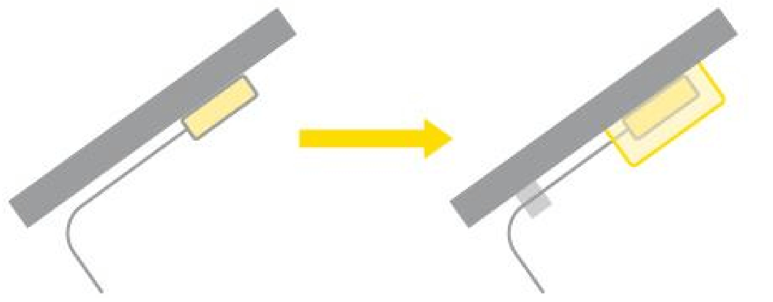
It is also recommended using an extra fixing with silicone or Sikaflex, particularly for module temperature above 75°C.
The sensor cable needs a cable grip close to the sensor housing.
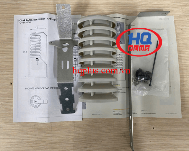
If mounted outdoors, avoid direct exposure to sunlight and rain to the sensor housing (aluminium block) and sensor case. If
necessary, provide protection from the sun and rain.
The through holes used to fix the sensor to a stable and suitable surface shall be accessible when the housing is opened. The
tightening torque of the case cover is 180 Ncm.
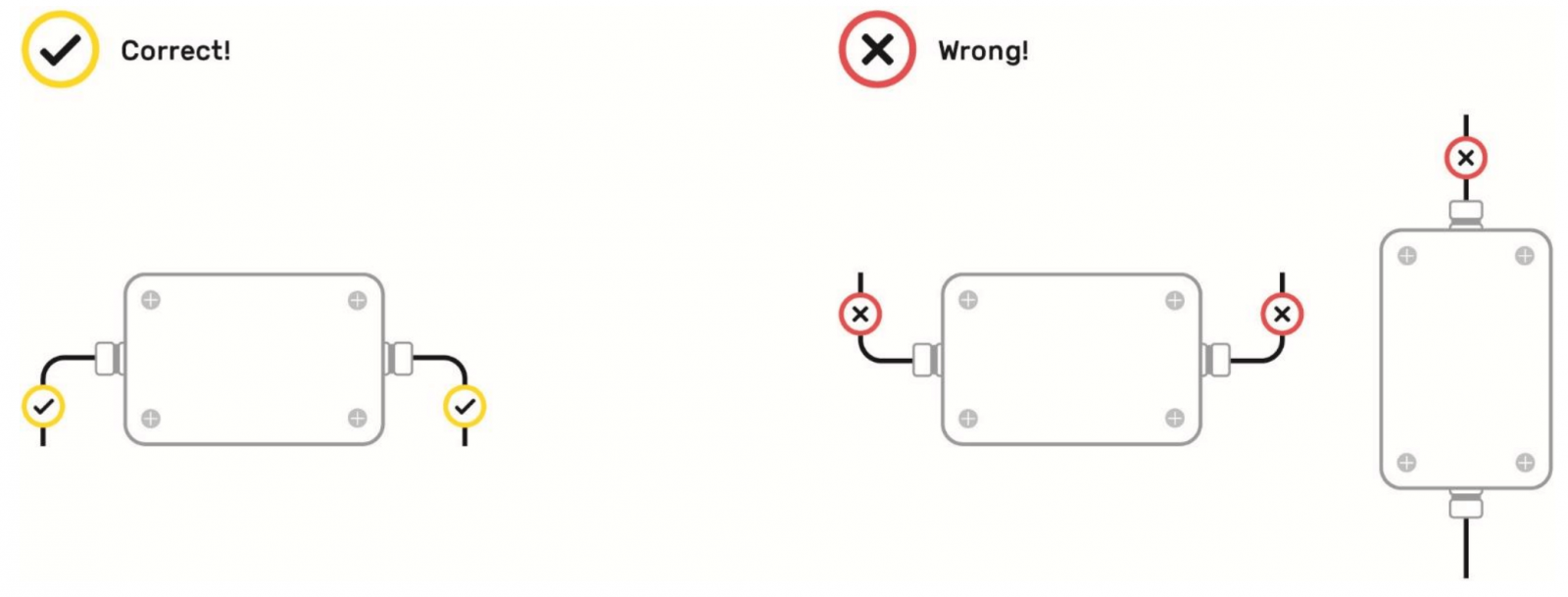
When installing the sensor, the cables must be routed downwards from the housing.
Electrical Connection
The sensors are designed for safety extra-low voltage (SELV) operation. The maximum power of the voltage supply
is 50 VA („Class 2 limited power“).
The cable shield shall be connected to the PE during installation.
WARNING: Connecting the supply voltage to the signal lines will damage the device
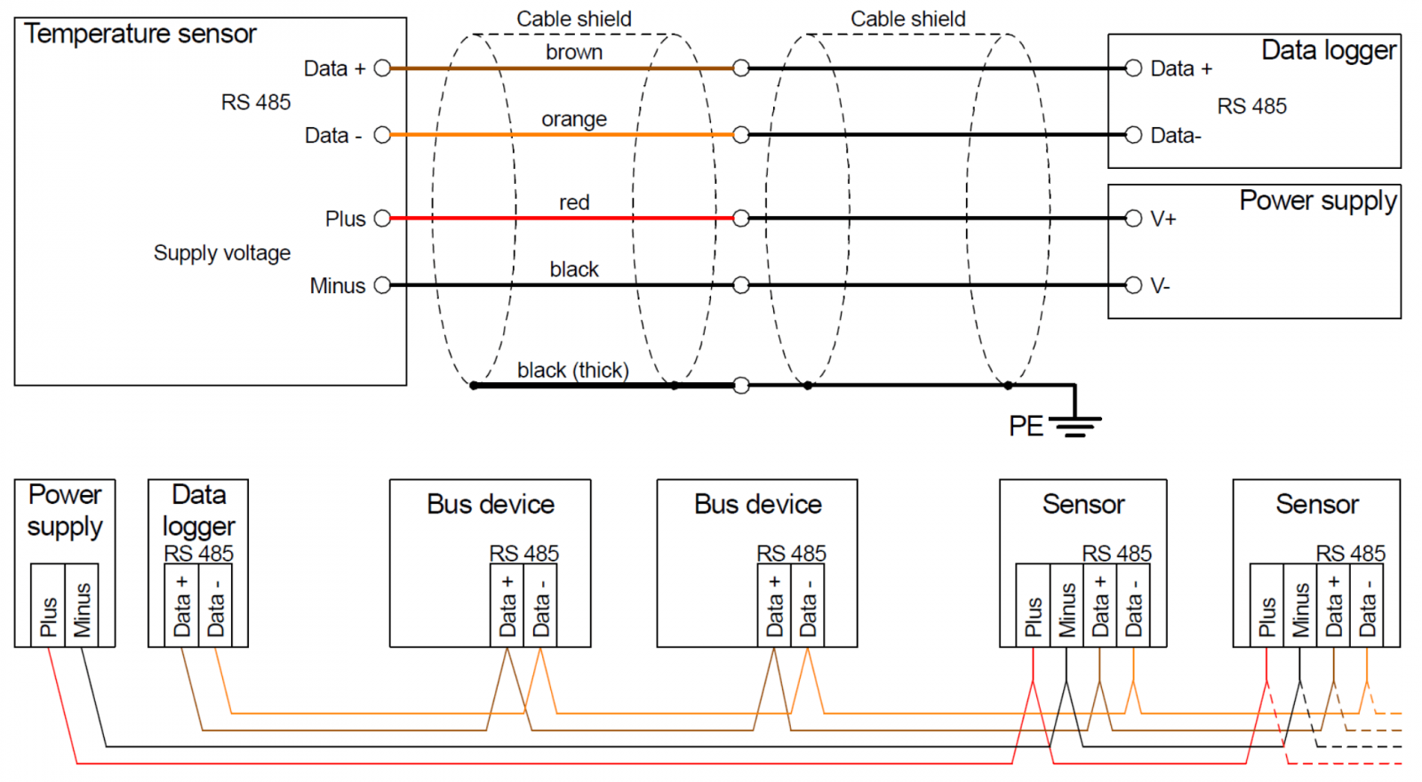
All MODBUS devices require the same bus parameter (baud rate, data format) but diąerent adresses.
Termination of RS485 bus usually is not needed.
Pin Assignment Cable Socket (only for Tm-RS485-A)
| Pin number | Signal |
| Pin 1 | RS485 – Data + |
| Pin 2 | RS485 – Data - |
| Pin 3 | 10 to 28 VDC |
| Pin 4 | 0 VDC |
Cable length
| Supply voltage | Cable cross section in mm² | ||||||
| 0.14 | 0.25 | 0.34 | 0.5 | 0.75 | 1.0 | 1.5 | |
| 24 VDC | 300 m | 600 m | 800 m | 1000 m | 1000 m | 1000 m | 1000 m |
| 12 VDC | 50 m | 100 m | 150 m | 200 m | 300 m | 400 m | 650 m |
Maximum additional cable length of temperature sensors with 6 m connection cable.
| Note: | If more sensors are supplied by the same voltage supply, the possible cable length is reduced accordingly. Example: 3 sensors at 24 VDC and cable 0.14 mm: 300 m / 3 = 100 m |
Maintenance
Scope of the regularly check (at least once a year): Cleaning, external damage, mechanical fastening, cable laying and any
damage to the cable.
Should damage be found that degrades the function or safety, the sensor is to be replaced.
A recalibration is recommended at least every 3 years.
Technical Data
| Output signal | RS485 |
| Measurement range | -40 to +90°C |
| Uncertainty (-40 to +80°C) | 1 K |
| Supply voltage | 24 VDC (10 to 28 VDC) |
| Current consumption | Typical 25 mA at 24 VDC |
| Galvanic insulation | 1000 VDC between voltage supply and RS485 |
| Sensor element | Pt1000 class A as per EN 60751 |
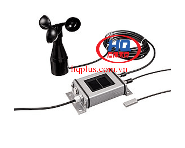
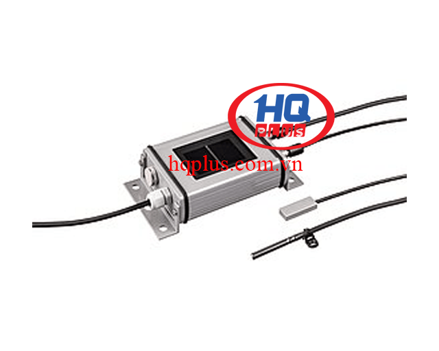
| Sensor element housing | Self-adhesive aluminum block, 35 mm x 12 mm x 6 mm |
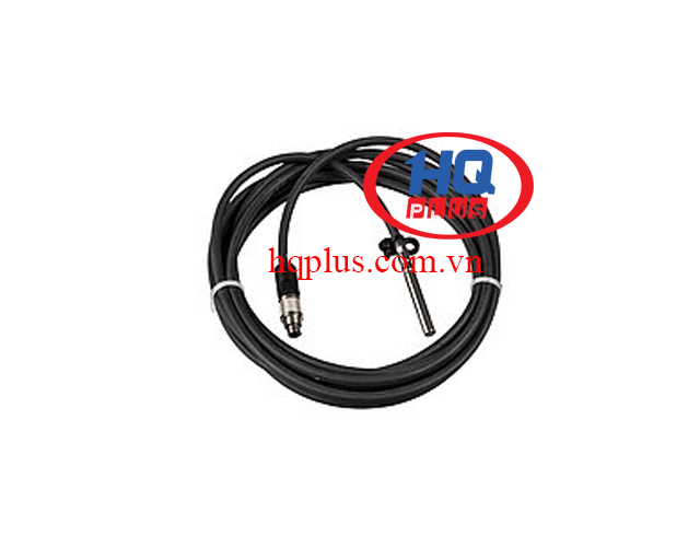
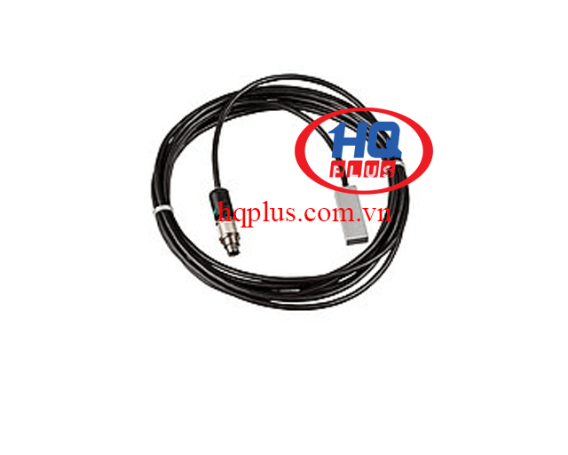
| Sensor cable (Pt1000) | Length: 3 m, PUR coated, shielded (LiYC11Y, 2 x 0.25 mm²) |
| Case material | Powder coated aluminium |
| Case dimension / protection level | 98 mm x 64 mm x 34 mm / IP 67 |
| Weight | 500 g |
| Operating temperature | Sensor element -40 to +90°C (see below installation instruction) Case -40 to + 80°C |
| Electrical connection | Length: 6 m, PUR coated, shielded LiYC11Y, 4 x 0.14 mm² |
| Protocol | Settings (default) | Note |
| Modbus (RTU) | Address: 1 Baud rate: 9600 baud Format: 8N1 |
Settings can be changed with „Si Modbus Configurator“ software. Maximum baud rate: 38400 baud |
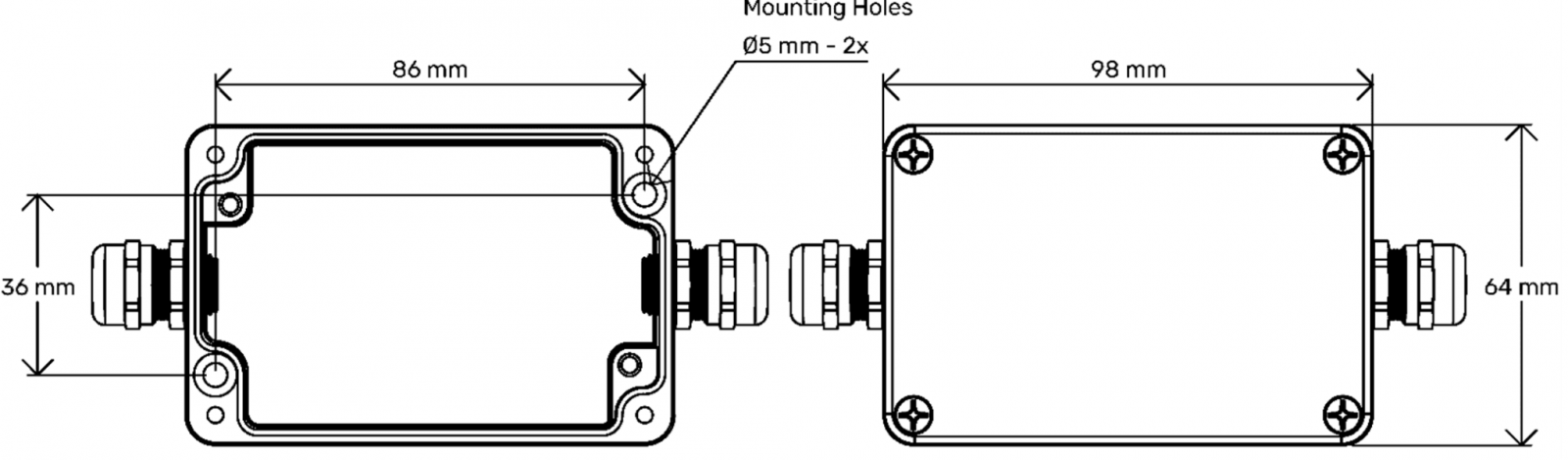
Dimensions
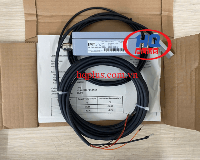
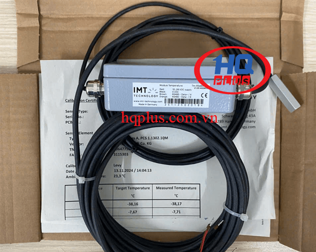
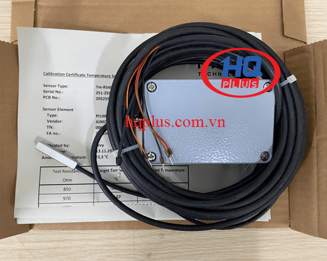
Scope of Delivery
· Sensor incl. pre-assembled connecting cable
· Calibration certificate for measurement electronic
· Instruction sheet